Energy savings in commercial heat treatment IV
Effect of heating type
Both for hardening and for tempering, we have to heat the parts properly. The entire heat-up cycle has 3 phases. Heating, equalization and holding at temperature. In the case of quenching, the temperature hold is the austenitizing time, in the case of tempering, then the tempering time, for annealing processes, then the annealing time. If any stage takes longer than necessary, then we are using energy inefficiently for the given purpose.
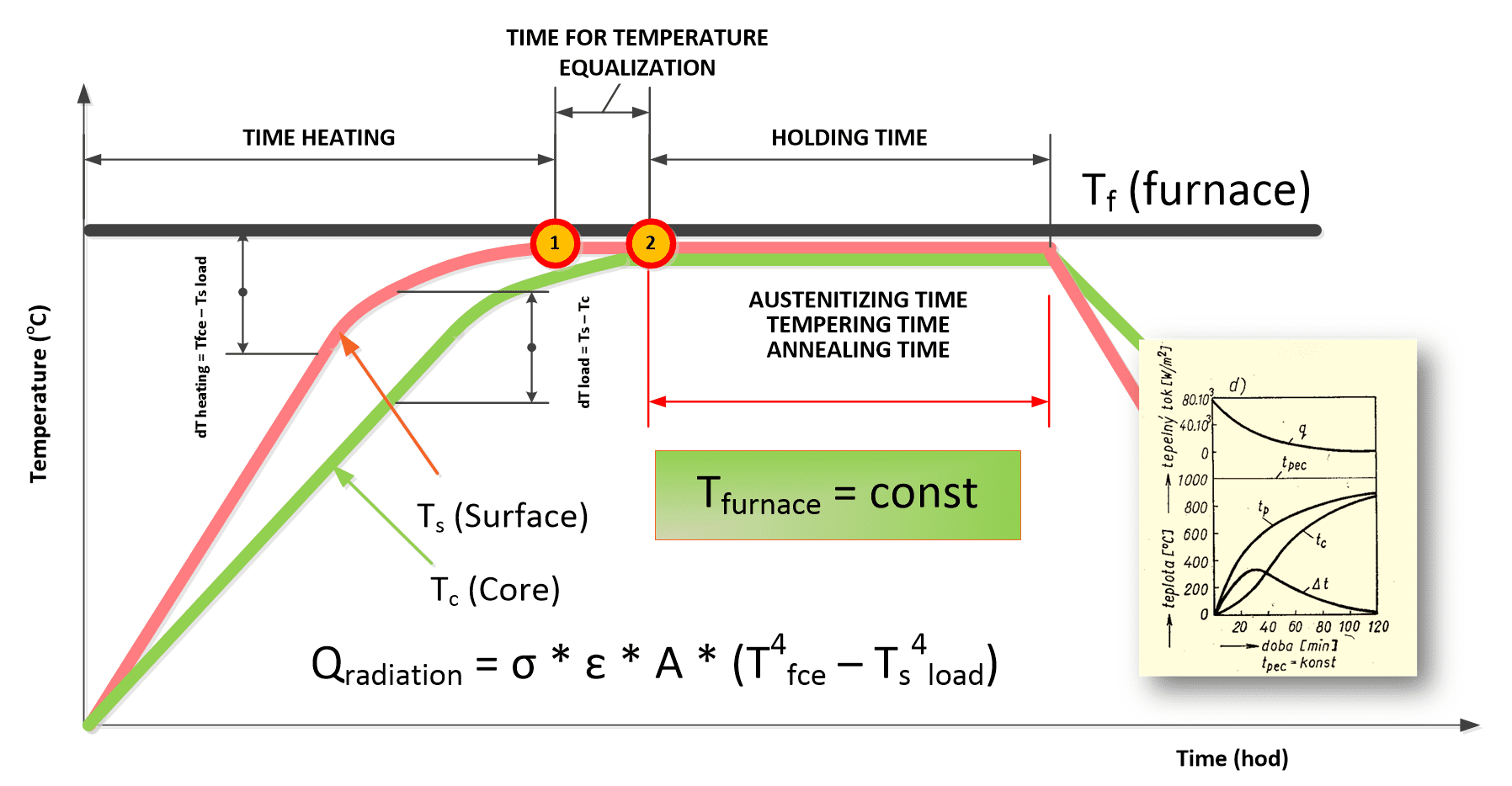
Fig. 1 – Heating of the load in a furnace with constant temperature and variable heat flow q(W/m2) [1]
From the point of view of practice, there are three demonstrative cases of heating:
- The furnace temperature is constant, but the heat flow to the load is variable depending on the dT between the furnace and the load (multipurpose furnaces, vacuum furnaces with two or more chambers, atmospheric chamber furnaces with a preheated chamber to the working temperature) – Fig. no. 1
- The furnace temperature is variable, the heat flow is approximately constant until the hold temperature is reached (single-chamber vacuum furnace) – Fig. no. 2
- Combination of the above two cases, so-called hybrid heating [1]
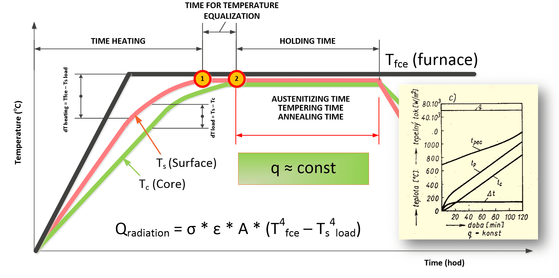
Fig. 2 – Load heating in a furnace with constant heat flow (W/m2) [1]
In the first case, the heating is very intense, especially in the initial phase, when the temperature difference between the furnace and the load is the largest. In the case of electric heating, however, we will not load ¼ of the maximum, because the consumption will be uniform and therefore more cost-effective. However, the disadvantage will be the large temperature difference between the surface and the core, and potential deformation or even stress cracks from the temperature difference. So, we will also have to consider Biot criterion, i.e. whether we are heating a thick or thin body.
In the second case, we will have a significantly lower temperature difference between the core and the surface, but we will have a problem with the control of the heat-up ramp, and thus also the consistency of all furnaces in the heat treatment plant within ¼ of the maximum extraction.
But since the radiation heat flow is directly proportional to the difference of the fourth powers of the temperatures (T4fce – T4load), then the heating time in the first case will always be shorter than in the second case at q= const and at a variable furnace temperature.
Heating in single chamber vacuum furnace
The ideal situation is with single-chamber furnaces (Fig. no. 3), where we can use thermocouples Ts and Tc. In that case, we measure the real situation in the furnace and by correctly evaluating the temperature of the furnace Tfce, the surface of the part Ts and the temperature of the core Tc we are able to evaluate the situation and respond to it by furnace programme. From the point of view of heat transfer, in this case it does not matter if the heat transfer is by convection or radiation, we only measure the result.
By using the so-called conditional dwell, we set the automatic time sequence of individual heating steps. Since these are programmed values, the furnace itself then checks that the holding time in steps 1, 2 and 3 are neither longer nor shorter than necessary. Heating will be economical and technologically correct.
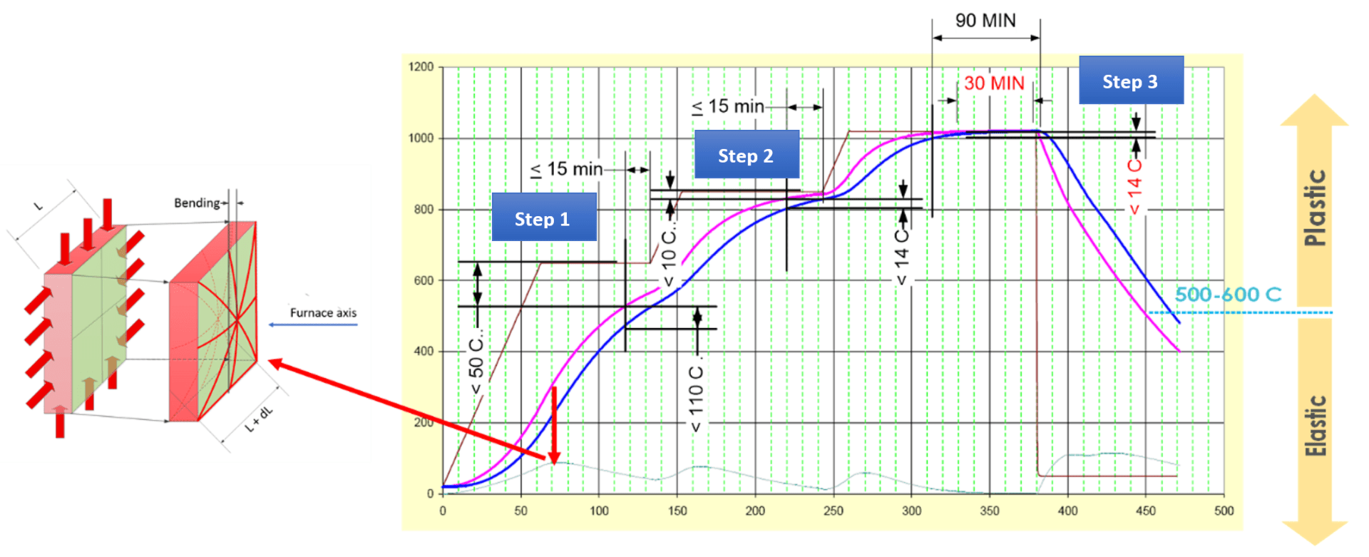
Fig. 3 – Load heating in a single-chamber vacuum combining mode of constant heat flow and constant furnace temperature
However, since working with batch thermocouples requires certain principles, related to the AMS 2750, rev. G, we have to pay attention to furnaces from the point of view of calibration. E.g. the state according to figure no. 4, when the furnace does not heat, will mean an infinite heating time and the related energy consumption.
The opposite case is overheating of the furnace, when, on the contrary, energy is apparently saved, but at the cost of high heterogeneity of the resulting properties due to the failure of the batch to heat up. And since we will either have to rework the batch or throw it away, we will have to mix energy costs for rework or claims. Both conditions are therefore undesirable and can only be eliminated by proper validation of the furnace
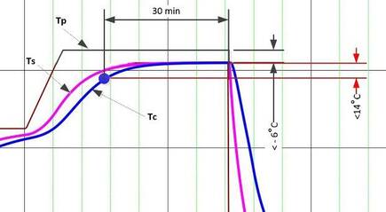
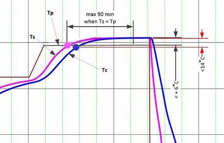
Fig. 4 – A typical furnace situation where the desired temperature will never be reached
Fig. 5 – A typical situation of the furnace, when the desired temperature will be reached earlier than technologically required
Heating in a multi-chamber or multi-purpose furnace
Figure No. 6 schematically shows the construction of the heating chamber of the multi-purpose furnace with a muffle.
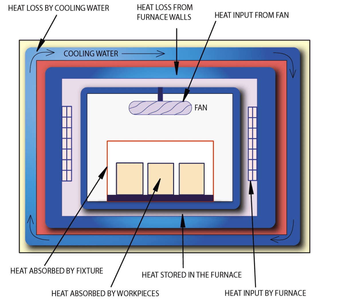
Fig. 6 – Schematic heat balance of batch furnace [2]
The convection component of the heating is provided by a ceiling fan, the radiation component is indirectly via a ceramic muffle, heated by a heat source depending on whether the furnace is heated electrically or by gas.
The first heating factor is radiant heat flow. Radiant heating is effective when there is a maximum difference between the temperature of the surface of the load and the furnace. It depends on the temperature difference between the source and the load in the fourth power. In the case according to figure no. 6, the temperature of the furnace is represented by the temperature of the internal ceramic muffle.
The second factor affecting heating is convection and the transfer of heat from the gas, which is usually forced to circulate in the furnace, using a fan. Today, in vacuum furnaces even under nitrogen overpressure, usually up to 1.5 to 2 bar abs., in atmospheric furnaces at a pressure of 1 bar abs. The heat transfer is proportional to the heat transfer coefficient and the temperature difference Tfce and Tld.
However, both heating components usually act simultaneously in the furnace, so we are talking about hybrid heating, and the heat flow equation will have the following form [2].

Where
Tfce – furnace temperature
Tld – load temperature
h – heat transfer coefficient
σ – Stefan-Boltzmanova constant 5,67 10-8 W/m-2K-4
ԑ – emissivity
In all cases, however, we have to decide whether bringing the load into a preheated furnace to working temperature will not mean its damage due to exceeding the limit values for tensile strength. Up to the temperature range between 500 C and 600 C, the heated bodies are in a rigid, elastic state, and Hooke’s law acts on them. This means that the parts are stressed by the temperature difference between the surface and the core. Only above 600 C does this stress problem gradually disappear, as the material becomes plastic. However, the real situation must always be evaluated with regard to the specific load (Fig. no. 7)
If we can use batch thermocouples Ts and Tc, this problem will be solved automatically for us by SW furnaces, permanently monitoring the temperature difference between Ts and Tc. If the permitted dTload is exceeded, the temperature heat-up is automatically reduced, or an extraordinary hold is inserted until the dTload difference is reduced.
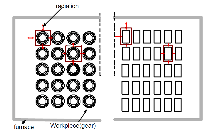
Fig. 7 – Heat transfer diagram for a real gear batch [3]
For furnaces where batch thermocouples cannot be used, we have to learn to work with Biot’s criterion. This is a number expressing the relationship between the heat flow qld, the thermal conductivity of the steel λ and the characteristic dimension of the part. If Bi < 0.25, it is a thin body, if Bi > 0.5, it is a thick body. In the case of thin bodies, the temperature difference between the core and the surface can be ignored, the stress limit values will never be exceeded.
Preheating
The situation is different for thick bodies. There, on the contrary, we always have to reckon with a critical state of tension (see Fig. no. 8). In order to avoid a situation where dT = Ts – Tc > e.g. 200 C, the batch can be preheated in a preheating furnace before being placed in the heating chamber.
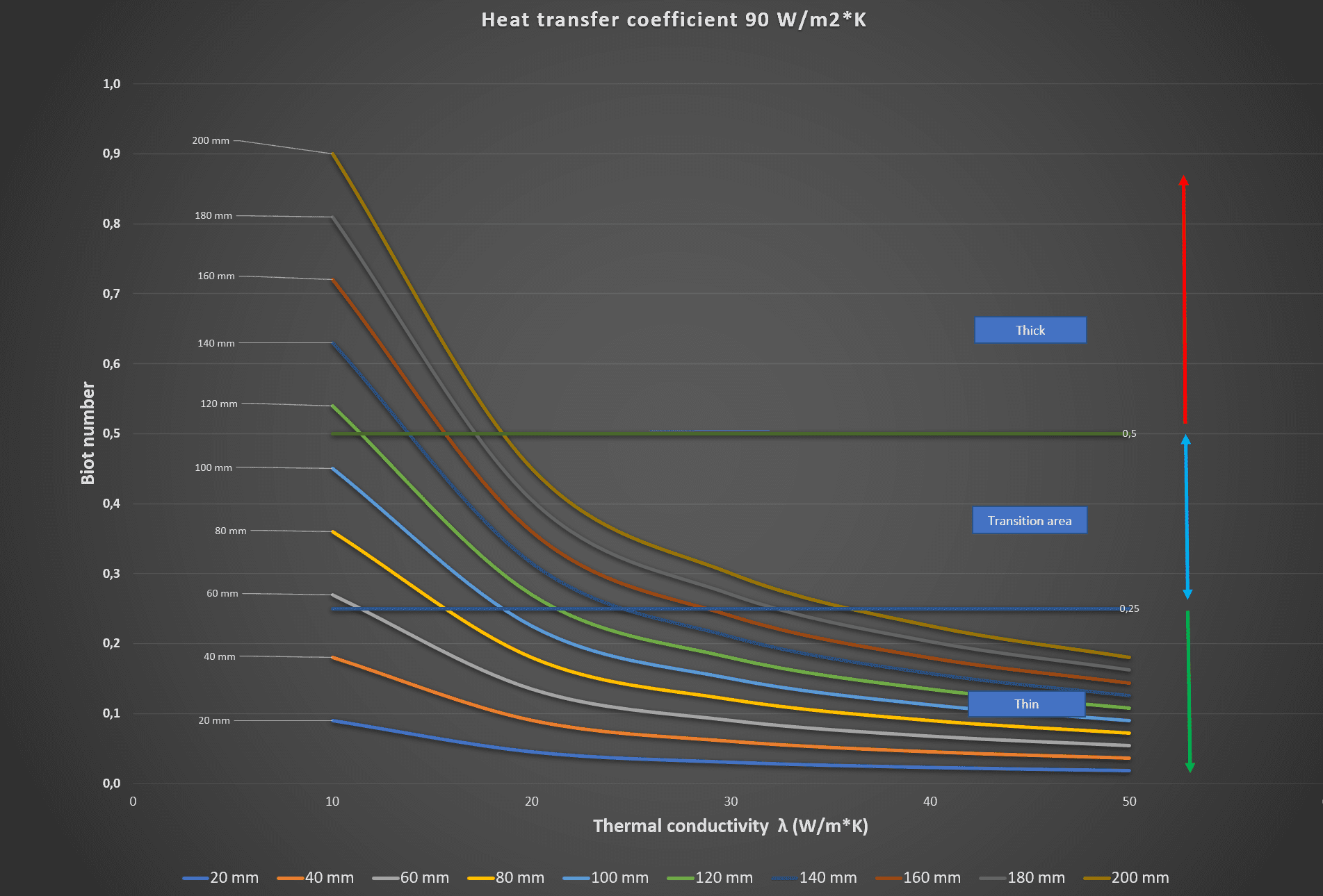
Fig. 8 – Calculation of the Biot criterion under the conditions of a heat flow coefficient of 90 W/m*K and different thermal conductivities from 10 to 50 W/m*K for diameters of 20 to 200 mm
We usually preheat in a tempering furnace without a protective atmosphere, with a protective atmosphere or in a vacuum furnace with convection heating up to 450 C. We then take the preheated batch in this way into the heated chamber of the multi-purpose furnace, not with a temperature of 20 C, but with a temperature of, for example, 450 C. According to some recommendations [4], the optimal temperature is 520 C due to high-quality pre-oxidation.
If we consider preheating to 450 C, then we will find that at low temperatures heat transfer by radiation is very small and the majority of the heat flow must be ensured by convection heating (Fig. 9). But what is interesting is that if we put a cold or preheated load to 450 C in the heating chamber of the quenching furnace, the heat flow will still be high, the difference between the two variants will be only about 5%. This follows from the fact that we either have 9504 – 204 = 8.15E+11 or 9504 – 4504 = 4.1E+10.
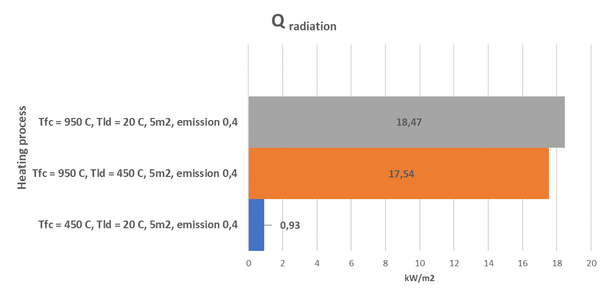
Fig. 9 – Comparison of the heat flow between the furnace and the load at an emissivity of 0.4 a) when placing in a furnace heated to 950 C, b) when placing a load preheated to 450 C in a furnace heated to 950 C c) when preheating the load to 450 C
If we take the heat balance for placing the load into the furnace heated to 950 C according to Figure No. 14, we will heat the body with the described dimensions and weight to the temperature in 105 minutes. With an average oven input of 50 kW, we get a consumption of 50*105/60= 88 kWh.
If we preheat the load, we need approximately 160 minutes to preheat to 450 C according to Fig. 12. The average input of the tempering furnace is 15 kW, so the consumption will be 15*160/60 = 40 kWh.
If we put the load preheated in this way into a furnace heated to 950 C, according to Figure 9, we will only need 5% less energy from radiation than if we started the load cold. So, it is 88*0.95% = 83 kWh. In total, we use 40 + 83 = 123 kWh to heat the batch with preheating. That’s 39% more energy.
What does this imply? Preheating does not work as an energy saving method for heating to the quenching temperature. It is better to put the cold batch directly into the heated heating chamber than to preheat it. Only if we have bodies with Bi > 0.5, and there are concerns about high internal stresses, we use preheating. Other reasons for using preheating are reduced deformations due to lower tension, pre-oxidation of the surface before carburizing or burning off residual impurities before low-pressure carburizing.
Preheating and preoxidation has one more pitfall. It changes the emissivity of the load surface ԑ. When the emissivity is increased from 0.4 to 0.5, the heat flow will increase to the values according to figure no. 10 by 25%,
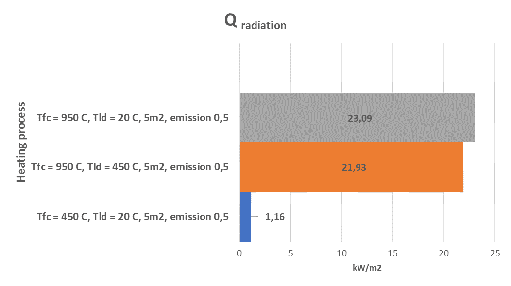
Fig. 10 – Comparison of the heat flow between the furnace and the load at an emissivity of 0.5 a) when placing in a furnace heated to 950 C, b) when placing a load preheated to 450 C in a furnace heated to 950 C c) when preheating the load to 450 C
Radiant and convective heating – comparison
When the load is preheated to 450 C, the share of heating from radiation will only be about 16%. The remaining 84% must be added to the load by convection. The following models show the difference in heating only by radiation (Fig. No. 11) and radiation with convection in the ratio of 20%/80% (Fig. No. 12)
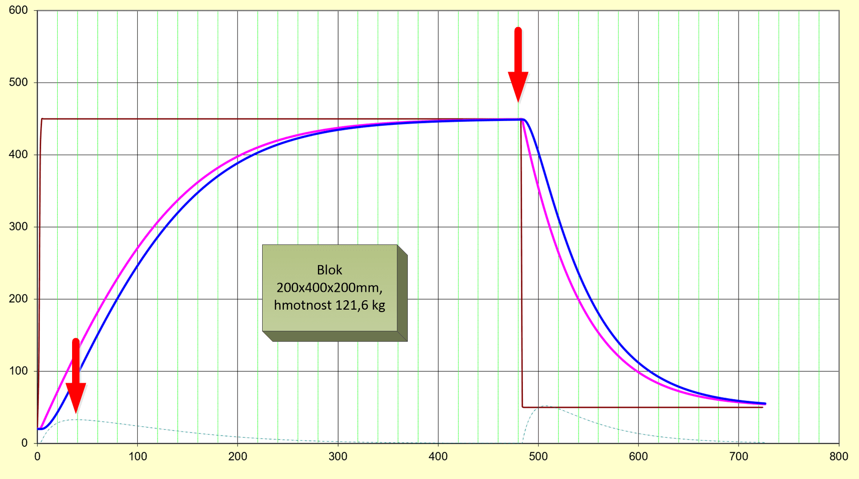
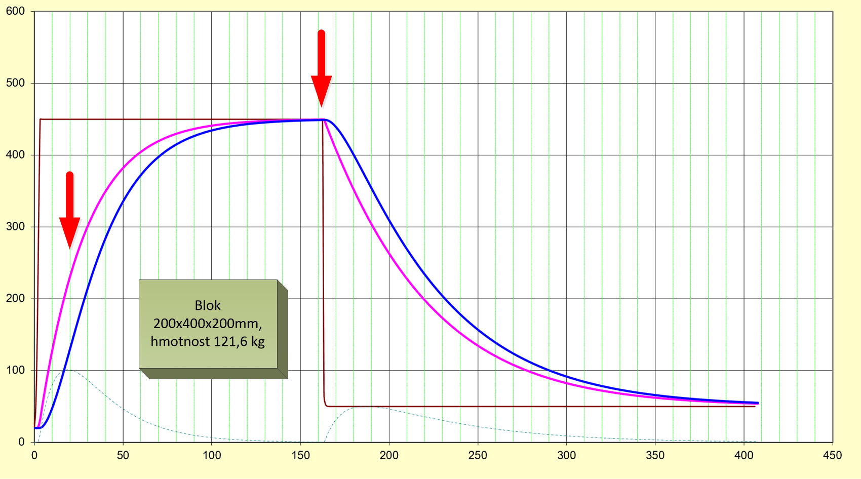
Fig. 11 – Preheating a 121.6 kg block to 450 C at 100% radiation, without convection heating
Fig.12 – – Preheating a 121.6 kg block to 450 C at 20% radiation and 80% of convection heating
It can be seen from the pictures that in the first case we will heat the batch for 480 minutes, in the second case only 180 minutes. In the case of pure radiation, the dTload difference will not exceed 50 C, and therefore there will be no problem with stresses, in the second case, dT will be close to 100 C and this is also acceptable. However, energy consumption is different. Whatever the input power of the furnace, the result of the heating efficiency will be in proportion to time.
And how is it when the load is placed in a furnace heated to 950 C?
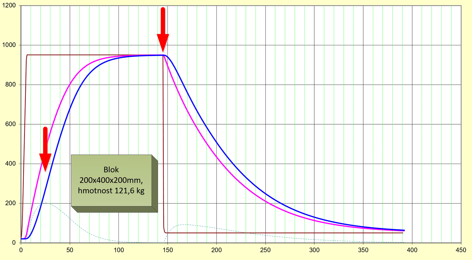
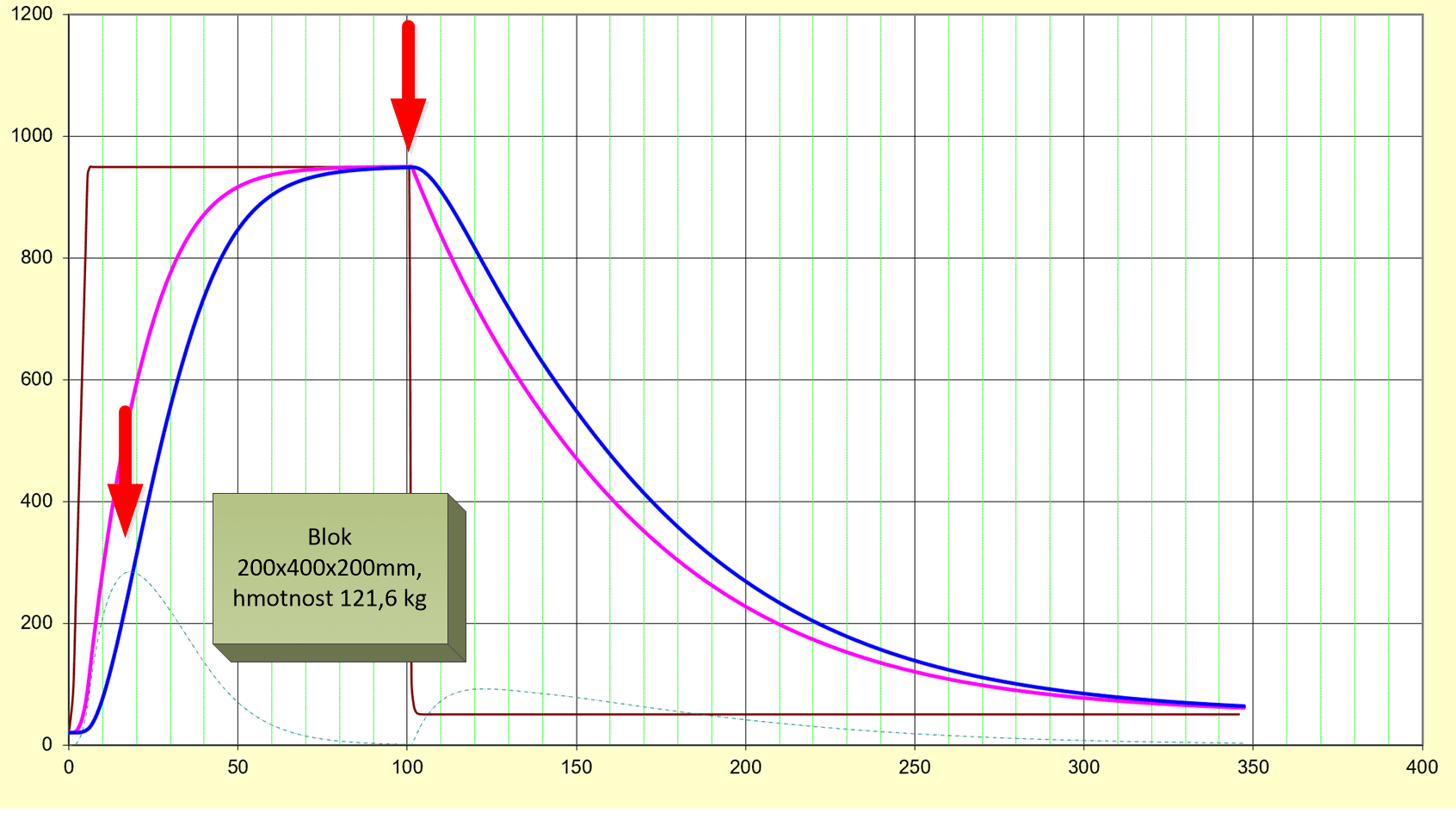
Fig.13 – Preheating a 121.6 kg block to 950 C at 100% radiation, without convection heating
Fig.14 – Preheat a 121.6 kg block to 950 C at 20% radiation and 80% convection
In the case of radiation heating, we need approximately 145 minutes (Fig. no. 13), in the case of heating with a high proportion of convection, then only 105 minutes (Fig. no. 14). But we have to be careful about the stresses, in the first case dTload will be roughly 200 C, in the second case with convection up to almost 300 C. This is already dangerous and we should not do without preheating.
So what does that mean?
- Heating in a furnace with a constant temperature is more advantageous, it does not matter if it is a multi-purpose furnace or a vacuum furnace with two or more chambers
- The radiation component is significant at high temperatures, but does not play a role during preheating. If we are even thinking about buying or upgrading a furnace, we must focus not only on the heat losses but also on improving the convection heating
- Preheating to 450 C and then placing it in an oven heated to 950 C consumes 40% more energy than if we omitted preheating completely
- The emissivity of the surface of the load for the transfer of heat by radiation plays an important role, the darker the body, the higher its absorption of thermal radiation. On the one hand, the heat flow to the charge will increase, but on the other hand, the danger from dTload when heated to 600 C will also increase. When the emissivity changes from 0.4 to 0.5, the heat flow will increase by 25%
[1] R.Kremer, J.Obroučka, Ohřev kovů/Metals heating, SNTL 1974
[2] Radhakrishnan Purushothaman Evaluation and Imorovement of Heat Treat Furnace model, 2008, https://digital.wpi.edu/downloads/ks65hc345
[3] Jin-wu Kan, Modelling and simulation of heat transfer in loaded heat treatment furnace, 2016
[4] Industrial Heating, Carburizing Process Control Boosts Productivity, Lowers Manufacturing Costs, https://www.industrialheating.com/articles/83907-carburizing-process-control-boosts-productivity-lowers-manufacturing-costs
January 24, 2023
Jiří Stanislav