Why do shaped inserts crack during hardening?
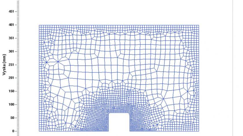
Sometime more than 20 years ago, I tried to find a model that I could show to the customer, and which could specify exactly why the shaped insert made by them cracks during hardening. So, we created a hardening model of insert from high alloy steel with a medium thermal conductivity of 30 W/mK, size 600×400 mm, hardened from an austenitizing temperature of 1050 C and cooled to a temperature of 20 C. For modelling was used Deform simulation software. Two cases were studied. The first with a notch in the middle of the bottom of the insert and with a radius R0, the second with the same shape but with a radius R10. The aim of the simulation was to clearly show 1) where the maximum of tensile stresses is and 2) what is the effect of radius size on stress.
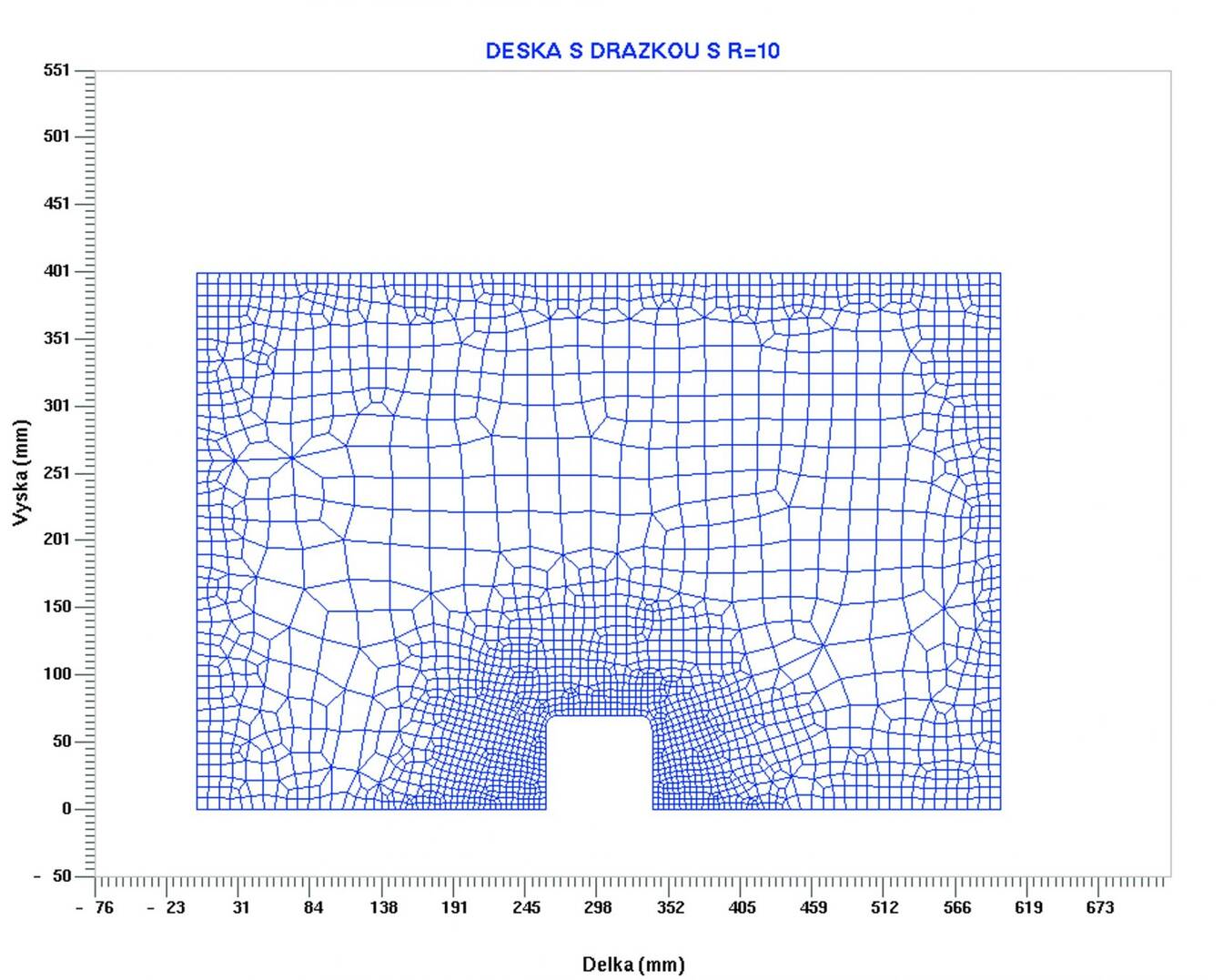
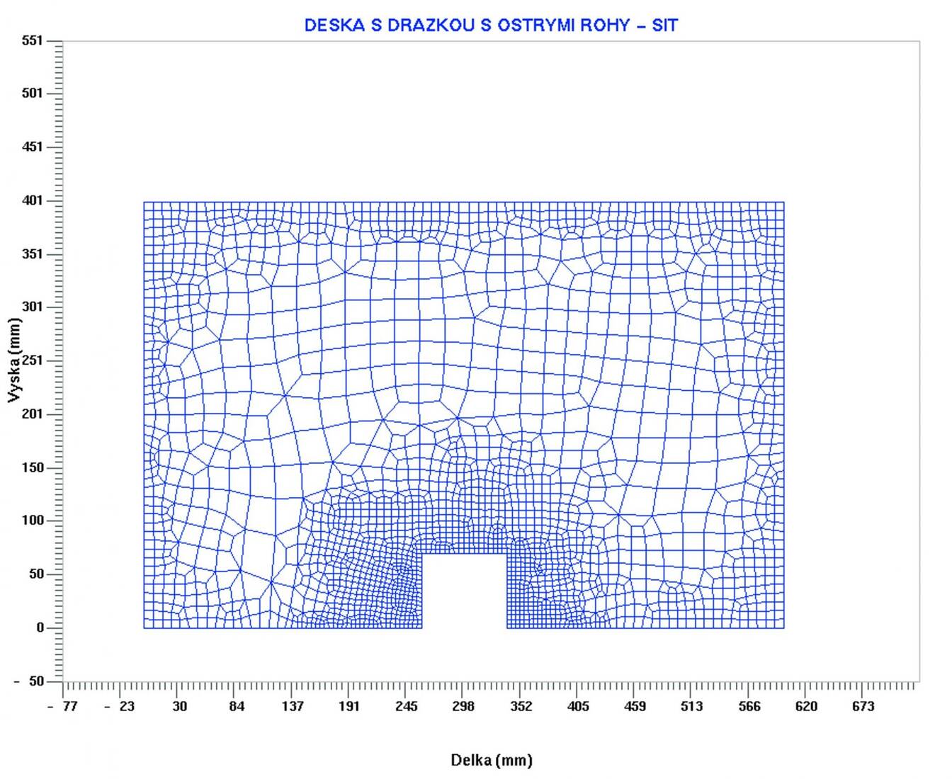
Fig. 1 – Computational network for radius R0
Fig. 2 – Computational network for radius R10
The result is shown in Figure 3. As expected, the greatest tensile stress is at the notch. Other tensile stress maxima are on the outer side of the insert, i.e., in places that most designers believe are not significant. The crack in the notch propagates at an angle of about 45 ° as a result of the superposition of tensile stresses in the “x” and “y” directions.
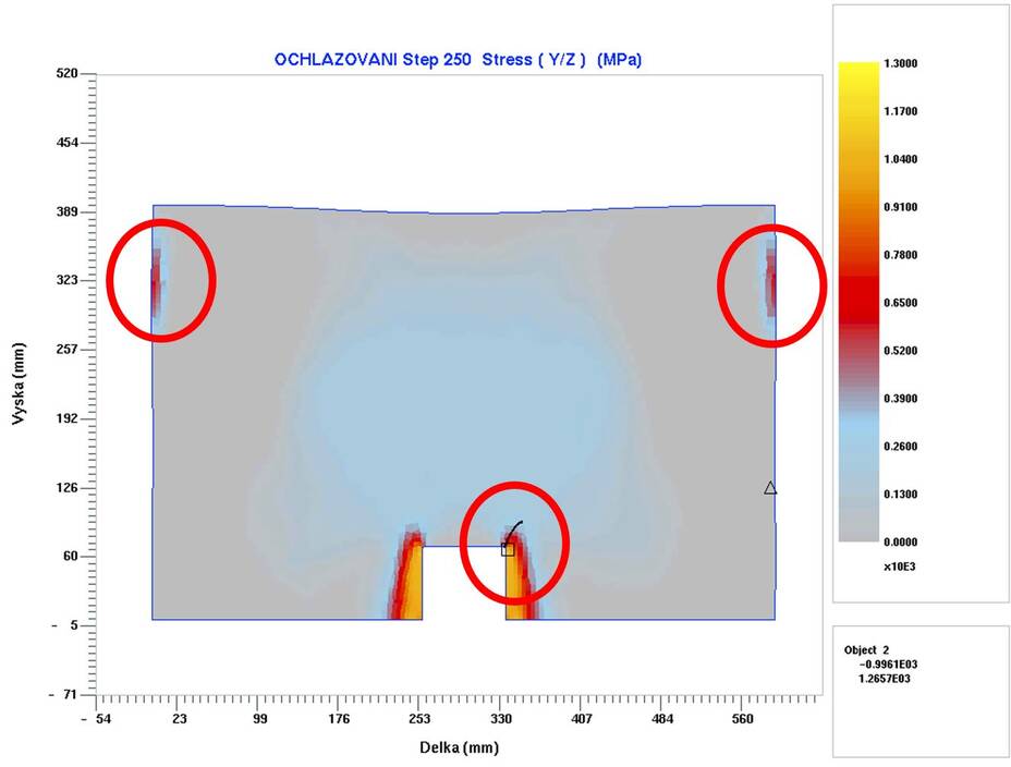
Obr. č. 3 – Tensile/compressive stress distribution during cooling from the hardening temperature
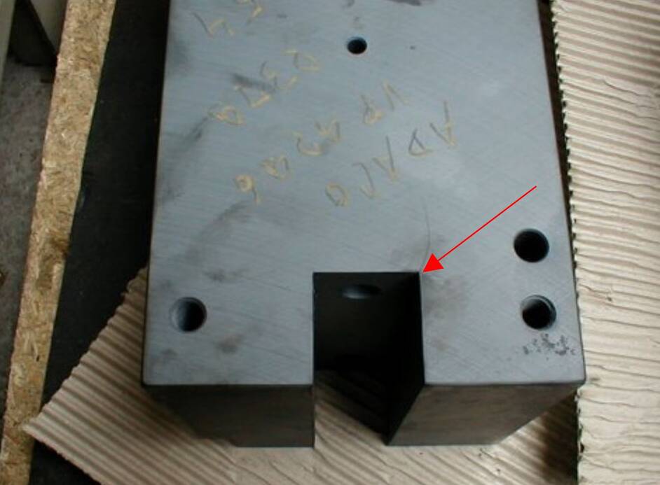
Obr. č. 4 – A practical example showing the concordance of a model on a real part made of material 1.2379
In terms of the result, I consider it most important that the model clearly shows that the critical points for hardening are on the outer side of the insert. In the middle of insert, where the designer places the shape of the final product, and which will then be the result of the injection or forming process, there are usually compressive stresses. These are not dangerous in terms of hardening. But it is precisely the cavity of the insert that the designer focuses on, because he wants his product to be exactly as it requested. But that often not enough. It is the outer side of the insert that is the source of danger and critical cracks, and it is up to the designer how to deal with it.
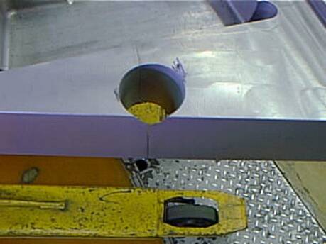
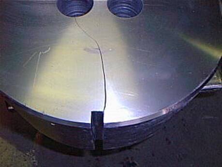
Fig. 5 – Example of a crack due to incorrect mounting of the inlet insert
Fig. 6 – Example of a crack formation from a clamping groove made without a radius
And what is the effect of the radius? Figure 7 shows the tensile stress at the notch for the radius R0, and Figure 8 shows the radius R10. From about 1150 MPa, the tensile stress drops to 780 MPa, i.e., by only 23%.
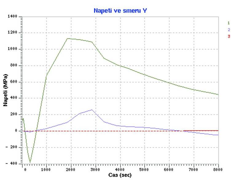
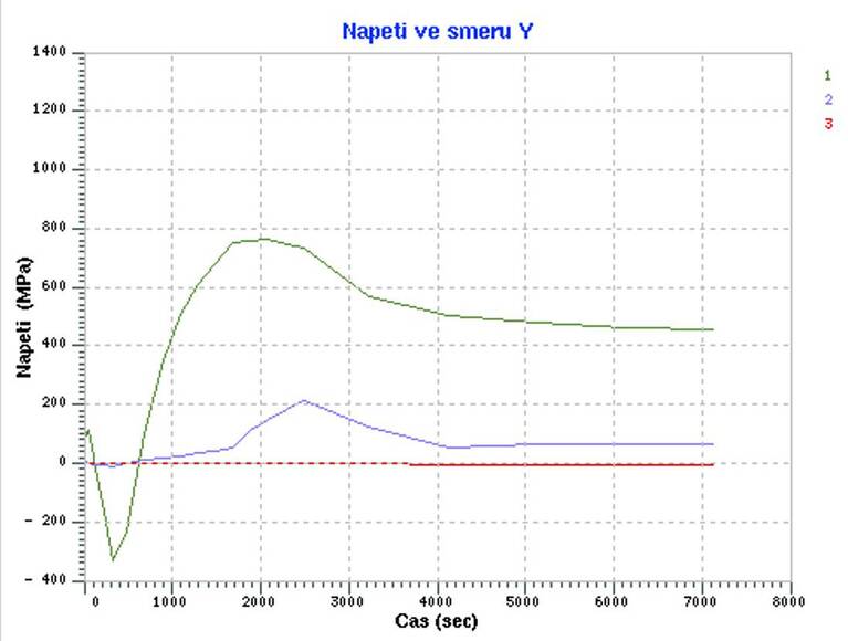
Fig. 7 – Tensile stress in “y” direction for radius R0
Fig. 8 – Tensile stress in “y” direction for radius R0 R10
So, the basic rule applies. To prevent the parts from cracking, we must eliminate all notches on the outer side of the insert, and at the same time we must apply the maximum possible radius. This is especially true for die casting inserts hardened according to Nadca 207, where we must cool for at least 28 C/min, regardless of stresses and deformation, because we have to achieve the correct internal martensitic structure of the material. It is then up to the designer how to treat these risks. The solution is also a two-step drawing, one for the preparation of the insert for hardening and the second for final shape. Of course, we must not forget about the quality of the material, but that is another chapter.
Liberec, 2nd of June, 2021
Jiří Stanislav