Heating of dies in a vacuum furnace, part II
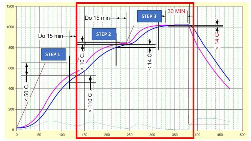
In the first part of the heating, we achieved that the inserts are heated to a temperature corresponding approximately to the setup furnace temperature Tp = 650 °C. However, the surface temperature Ts may not reach the furnace temperature Tp and will lie somewhere in the interval Tp> Ts> Tc. The temperature in the core Tc then decides on the start of the hold time countdown. It does not have to be significantly long; the goal is to heat the parts in full cross-section above 600 °C so that the material of the insert goes into a plastic (ductile) state. Usually, after reaching the difference Tp – Tc < 50 °C, when the condition Ts – Tc <110 °C is automatically met, a holding of 15 minutes is set. Its extension makes no sense and is uneconomical, because by reducing the temperature difference Tp – Ts and Ts – Tc, the heating efficiency is reduced. Our interest is not only the proper heating of components in the furnace, but also the economics of this heating.
Just to give you an idea, for possible calculation it is necessary to take into account the heat transfer by radiation between the heating elements and the heated parts, expressed by the equation in which the temperatures are in the fourth power Q = σ * ε * S * (Tg4 – Ts4) [W], where Tg is the temperature of the graphite heating elements, σ represents the Stefan-Bolzmann constant, ε the emissivity of the surface, and S then the irradiated area.
Furthermore, it is necessary to take into account the heat transfer from the gaseous medium to the surface of heated parts according to the equation for convection heating Q = α * S * t * (Tp – Ts) [W], where α is the heat transfer coefficient for the given environment, and at the same time heat inside the components according to the relation Q = λ * S * (Ts – Tc) / d [W], where λ is the coefficient of thermal conductivity for a given steel, which is not constant and changes with the heating temperature, and d is the wall thickness.
In all these equations, therefore, there is a difference in temperature, but most significantly in the transfer of heat by radiation, when the temperatures are in the fourth power. Therefore, more important than dealing with the theoretical calculation is to measure temperatures with thermocouples Ts and Tc, and to control the heating process from these thermocouples.
When programming the individual heating steps on a vacuum furnace, the so-called conditional dwell is usually used. In practice, this means that meeting a condition triggers the required step. However, since most vacuum furnaces do not have such programming capabilities, it is necessary to find a heat treatment supplier who has furnaces so programmable. The usual trigger for the heating step is one of the thermocouples, in our case Tc. When the difference Tp – Tc < 50 °C is reached, the step time starts automatically.
Whether Ts in the first step reaches a temperature Tp = 650 °C is therefore not decisive, it is decisive that the previous condition Tp – Tc < 50 °C is fulfilled. After its fulfillment, it is possible to continue heating, regardless of the temperature Ts, but with the knowledge that the optimal temperature difference between the heating elements and the surface Ts will be guaranteed. Thus, the heating will be sufficiently efficient according to the above equation for heat transfer by radiation.
However, since by fulfilling the condition Tp – Tc < 50 °C it is confirmed that Tc > 600 °C, it is thus also confirmed that the heated material is already over the transit temperature of the transition from solid to plastic (ductile) state and is therefore heated to the temperature range, where it is no longer necessary to take into account dT, and thus also the stress from the temperature difference dT = Ts – Tc.
In the next heating phase, for a hold on Tp = 850 ° C, we can heat the parts at any speed and the heating ramp for this second delay can be significantly higher than for heating up to 650 °C. If in the first step up to 650 °C it is usually 6 -10 °C/min, and it is additionally controlled and limited by a ramp to Tc <220 ° C / hour = 3.66 ° C/min, then in the second heating step to 850 °C we can set a ramp of 10 to 20 °C/min on the furnace and we no longer have to check the ramp on Tc.
The aim of the second hold at 850 °C is therefore not to reduce the stress in the heated parts, but only to thermally homogenize the material before we start heating it to the austenitization temperature.
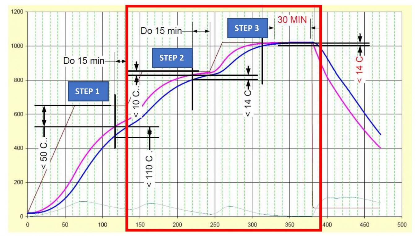
Fig. 1 – Theoretical (ideal) diagram of heating of dies in a vacuum furnace
Simultaneously with the heating of the material of the parts, some other properties of the steel also change. Above all, its thermal conductivity changes. It increases for high-alloy steels, but decreases for low-alloy steels. However, once we reach temperatures above 700 °C (Fig. 2), the thermal conductivity for all types of steels is essentially the same and stabilizes at 25 – 30 W / (m.K). This is also an advantage for further heating, since all types of steels can be processed in the same way from the point of view of heating at this stage.
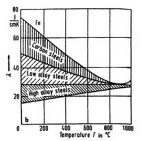
Fig. 2 – Dependence of thermal conductivity of steel on temperature (Totton’s Steel Heat Treatment Handbook)
The hold at 850 °C is again controlled from the thermocouple Tc. However, as soon as we reach the temperature Ts – Tc < 14 °C on the part, we should start counting down the dwell time. However, since usually the conditional delay evaluates the difference Tp – Ts or Tp – Tc, and not the difference Ts – Tc as Nadca 207 says, we will deal with the fact that again the condition of the transition to the next step will be reaching the temperature on Tc.
The surface temperature Ts will again be in the interval between Tp> Ts> Tc, but the temperature difference range will be narrowed to only 14 °C. Even in this phase of heating we do not have to wait until Ts reaches the furnace temperature Tp, but it is likely that the temperature difference Tp – Ts will be less than 10 °C. The holding timer at temperature can again be minimized, eg for 15 minutes.
The last heating step is heating to the austenitization temperature. This is the most important temperature of the entire heating process. We must ensure that the heated parts reach this temperature as far as possible over the entire cross-section, the holding time must be long enough to dissolve the carbides in the steel as best as possible, and at the same time not long enough for the primary grain growth. Nadca 207 therefore defines this heating phase as 30 minutes from the moment when Ts – Tc < 14 °C, and at the same time states that it must not be longer than 90 minutes from the time when Ts reaches the temperature Tp.
If we work in the mode of Nadca 207, then the austenitization temperature is not defined by the temperature range From-To, but only by a single temperature according to Nadca 207. It is necessary to be very careful. The material sheets of steel manufacturers always refer to the temperature range for austenitization, but this range cannot be applied to die-castimg inserts processed according to Nadca 207. The specification of austenitization temperatures, as well as the determination of heating delays are given in the Nadca 207 table on page 34.

Fig . 3 – Part of the table with temperature specifications from Nadca 207, page 34
As an example, I mention steel W300 ISOBLOC from Bohler (Nadca 207, type H11 / 2343, steel group D), where in the material sheet the range of hardening temperatures from 1000 to 1040 °C is allowed, but Nadca 207 allows only one temperature, 1000 °C.

The ramp for heating to the austenitization temperature can be chosen again significantly higher, as in the previous step, there is no danger of stress from the temperature difference Ts and Tc.
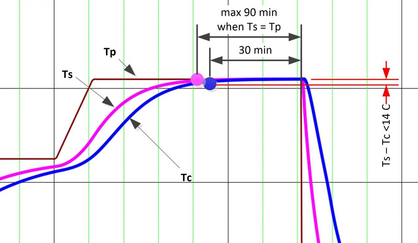
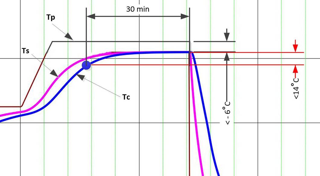
Fig. 4 – Ideal heating process
Fig. 5 – Heating process, when the load thermocouples never reach the required temperature
The ideal heating process is shown in Figure 4, where Tp is the programmed furnace temperature, Ts is the surface thermocouple temperature and Tc is the core temperature. All 3 temperatures meet at the required temperature, e.g. 1000 °C. The austenitization time 30 minutes from reaching Ts – Tc < 14 °C starts to count down as expected, as well as the limit time of 90 minutes from when Ts reaches temperature Tp.
But Figure 5 shows another, not unusual, example. The furnace does not heat up and neither Ts nor Tc ever reach the desired temperature Tp. Because Nadca 207 does not give us the possibility the austenitization temperature tolerance, failure to reach the value Tp = 1000 °C can be considered as faulty austenitization. The condition that the austenitization time will be a maximum of 90 minutes from reaching the temperature Ts = Tp will never be met, only the condition Ts – Tc < 14 °C and the time 30 minutes will be met and the process will require manual intervention by the operator.
Because the vacuum furnace is usually validated according to AMS 2750 F, it can be assumed that the desired and actual temperature in the furnace, controlled by a control thermocouple, will actually be 1000 °C. However, since the furnace is in Class 2, with a temperature tolerance of +/- 6 °C, a situation may occur where the part with Ts will be loaded in the furnace heat chamber, where the temperature is within the tolerance band for TUS, but with the limit temperature near deviation -6 °C. The processed part itself will therefore not be at a temperature of 1000 °C, but only at a temperature of 994 °C. However, this is only provided that the batch thermocouples show the correct temperature. However, other cases may occur.
- The furnace does not have a valid TUS or SAT, so it is possible to doubt the furnace temperature,
- The control thermocouple is incorrectly positioned in relation to the heating elements and therefore the furnace does not heat correctly or overheat
- Load thermocouples are without calibration, so it is not clear if there is a measurement error in them
- The offsets setup for the individual thermocouples are incorrect or no longer valid
- The furnace was overloaded for the given processing, so the temperature was not actually reached at the place of measurement by load thermocouples
- Improperly prepared holes for inserting Ts and Tc
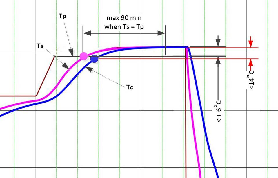
Fig. 6 – Heating process when the load thermocouples exceed the required furnace temperature
Just as the furnace does not heat, in case of incorrect calibration it can overheat (Figure. 6). At the set furnace temperature Tp = 1000 °C the parts will be heated to a temperature +6 °C higher than the furnace temperature. Thus, instead of the required 1000 °C, they will have 1006 °C. The opposite problem occurs. As soon as Ts reaches the furnace temperature Tp, a time of 90 minutes is started, checking that the maximum austenitization time. However, since the condition that Ts – Tc < 14 °C be met later, the step may end after 90 minutes have elapsed, even before the austenitization time of 30 minutes has elapsed. The consequences can be fatal, e.g., in that the hardness after hardening will be significantly heterogeneous, precisely due to the premature termination of austenitization.
How to deal with this? Because Nadca 207 does not set a tolerance band for austenitization temperatures, this tolerance is ZERO, so it must be taken as a critical condition. However, Nadca 207 says that the furnace must be maintained in a calibrated state according to AMS 2750 in the latest version, with maintained temperature recording devices, with load thermocouples validated also according to AMS 2750, and inserted in heat treated parts according to Nadca 207. Furnaces for hardening inserts for die casting, they should not be overloaded and the batch should not exceed 50% of the allowable weight of the furnace.
If these conditions are met, it is likely that the hardening cycle will take place according to Figure 4, while the austenitization temperature will be reached within the tolerance of furnace Class 2, +/- 6 °C. However, since the processing quality according to Nadca 207 is based on individual impact tests, these impact tests will show whether the austenitization temperature in the range of 994 to 1006 ° C had an impact on the processing quality. It is then up to the heat treatment shop to assess the resulting risks, because if the impact tests are not in the required values, the heat treatment provider is authorized to perform one repeated hardening, after previous soft annealing, and if even after this re-hardening the impact values are not correct, the heat treater will cover both the costs and the resulting damages. Of course, provided that the entrance tests of the material at the entrance to the tool shop were OK.
However, there are other, technical possibilities related to the application of AMS 2750 F. As soon as new load thermocouples are used, today usually type N, the furnace should have new SAT with these thermocouples, and if required by the test results, then set corresponding offset. However, the condition applies that the offset must not exceed the tolerance range of the furnace, in this case Class 2, +/- 6 °C.
There are other software options to circumvent this problem, e.g., by setting allowed dT in the austenitization program step to reach the furnace temperature Tp on the load thermocouple Ts in the range +/- 6 °C. In the case of the cycle according to Figure. 5, i.e., for a furnace that does not heat, this means that the time of 90 minutes starts after reaching Ts = Tp – 6 °C. This will allow the cycle to run automatically, but will not change the fact that the austenitization temperature will be only 994 °C and not the required 1000 °C.
The cycle can be approached in the same way with an overheating furnace. On Ts we set the condition Ts = Tp + 6 °C, and in that case the time of 90 minutes starts to count down when Ts reaches a temperature of 1006 °C. Again, the austenitization time will be respected, but the temperature of the parts will not be 1000 °C, but 1006 °C.
Although I believe that Nadca 207 should tolerate non-compliance with the austenitization temperature within the temperature tolerance for furnace Class 2, as this is not the case, care must be taken very carefully to calibrate the furnace on all thermocouples entering the process and make every effort to so that the resulting records from the process run according to the ideal state in Figure 4.
In any case, at the moment when the furnace shows the state according to Figure 5 or 6, it is necessary to perform at least a new SAT and verify how the furnace actually behaves according to AMS 2750 F. The heat treatment plant must keep records of all these facts, as well as of the set offsets. If necessary, testify to the customer that the furnace validation is performed at the prescribed intervals and that the set offsets are current and do not deviate from the values according to AMS 2750 F.
2nd of August, 2021
Jiří Stanislav