Gas Quenching in vacuum furnace – part III
In parts I and II, I described the heating phases, the aim of which is to heat up the parts to the austenitization temperature and then to homogenize them well before the quenching itself. These heating phases must take place automatically, without the intervention of the furnace operator, and regardless of the size or shape of the parts.
Similar requirements are for the cooling phase, resp. for quenching, when we need to cool down the parts quickly from the austenitization temperature. This sequence of the processing cycle must also take place automatically, without operator intervention, and regardless of the size or shape of the inserts.
If we have a furnace in which we can control the hardening cycle with Ts and Tc, we have correctly placed load thermocouples Ts and Tc, then the secret of optimal cooling lies in the correct evaluation of these temperatures and in monitoring their temperature difference dT = Ts – Tc. As with heating, it must be taken into account that the hardened steel with temperature above about 500 °C is in a plastic state, below this temperature in an elastic state. Below ≈ 500 °C, we must also take into account the stresses from the temperature difference, and below ≈ 300 °C, the transformation stresses from the change from austenite to martensite are added to this.
At the same time, we must know the CCT diagram for hardened steel so that we can exclude structural phases that reduce the impact strength of quenched and tempered steel. This is mainly an undesirable precipitation of carbides, as well as the proportion of bainite or perlite in the structure. Thus, so we have to control the cooling to miss the area of carbide precipitation for a given steel ①, and at the same time so that we do not enter the area of bainite at all or minimally.②. However, since the carbide or bainite precipitation curves are individual for each steel, the hardening process should be modified with respect to the type of steel being processed – see Figures 1 and 2 for H11 and Dievar steels.
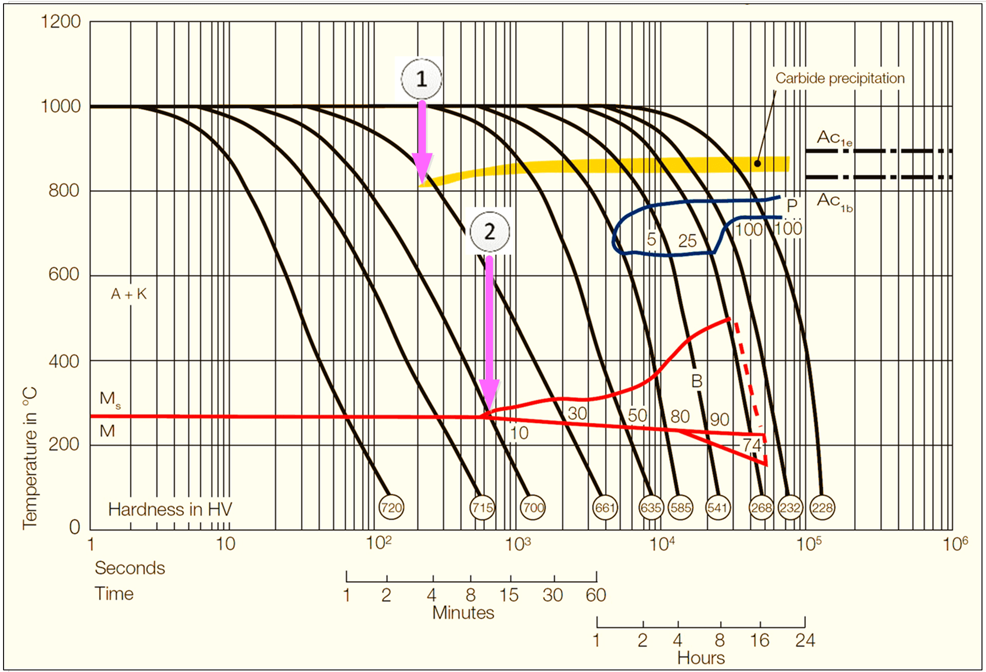
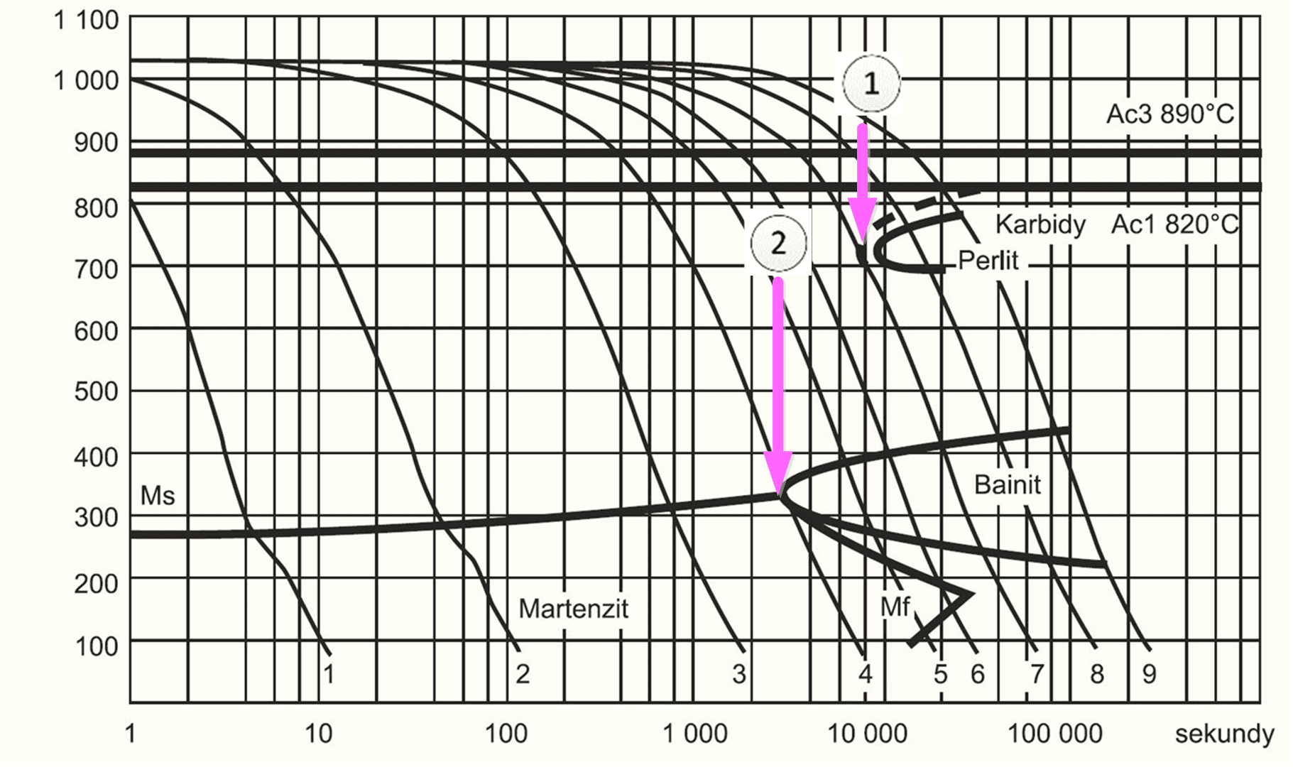
Fig. 1 – CCT diagram for USN steel (1.2343) with marked critical points ① and ②, source Kind & Co
Fig. 2 – CCT diagram for Dievar steel with marked critical points ① and ②, source Uddeholm
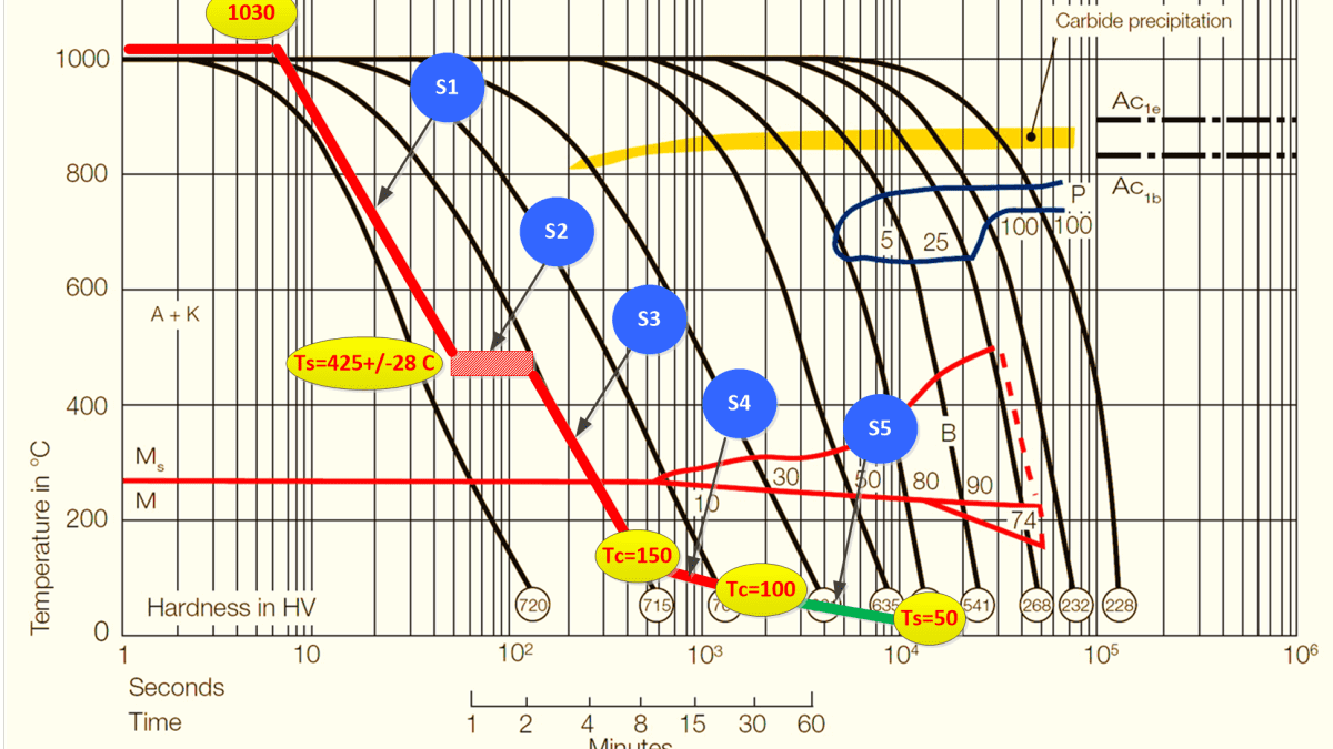
Figure 3 shows the quenching cycle, split into five separate steps and set in the CCT diagram for USN steel (H11). Every step has its meaning and cannot be bypassed or ruled out. The first step S1 serves to obtain the necessary internal structure of the material. If we were to cool directly to eliminate precipitation of carbides, we must move to the left of point ①, and to avoid bainite to the left of point ②. For materials of type H11, H13 or 1.2367, this means a high cooling rate, at least 28 °C/min according to Nadca 207. However, as can be seen from the CCT diagrams, optimal structures can be achieved for Dievar steel even at lower cooling rates, even if in Nadca 207 this is not mentioned.
In the next steps S2..S5, we must focus not only on the requirements for the structure, but also on ensuring that the parts do not crack during hardening. Therefore, in step S2 it is necessary to apply the so-called isothermal holding. Its aim is to reduce the temperature difference between Ts and Tc, and thus the stresses associated with this temperature difference, even before the material changes from a plastic state to an elastic state by cooling.
According to Nadca 207, the isothermal hold must be set at 425 +/-28 °C. For hardened parts, this means waiting for the time when the temperature difference Tc-Ts falls below 110 °C, e.g., at a set temperature of 450 °C. However, the isothermal holdimg cannot be extended arbitrarily with regard to the possible transition to bainite ②, and therefore its duration according to Nadca 207 is limited to 30 minutes. Otherwise, it must end automatically. Another condition for the isothermal holding is that it must be terminated even if the surface temperature Ts falls below 400 °C.
Since the temperature change in the hardened part takes place relatively quickly, it is clear that these changes must be detected by the furnace control system and then corrected for the behaviour of Ts and Tc automatically, without operator intervention.
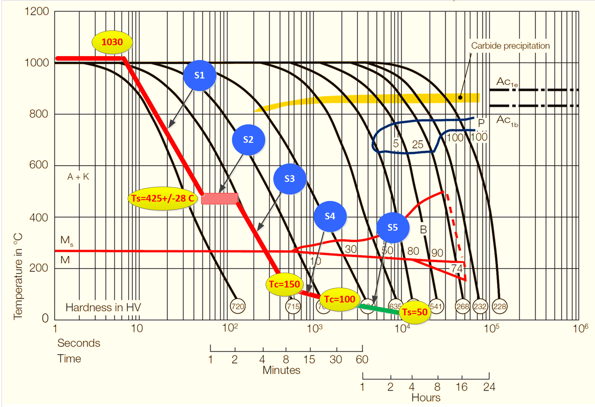
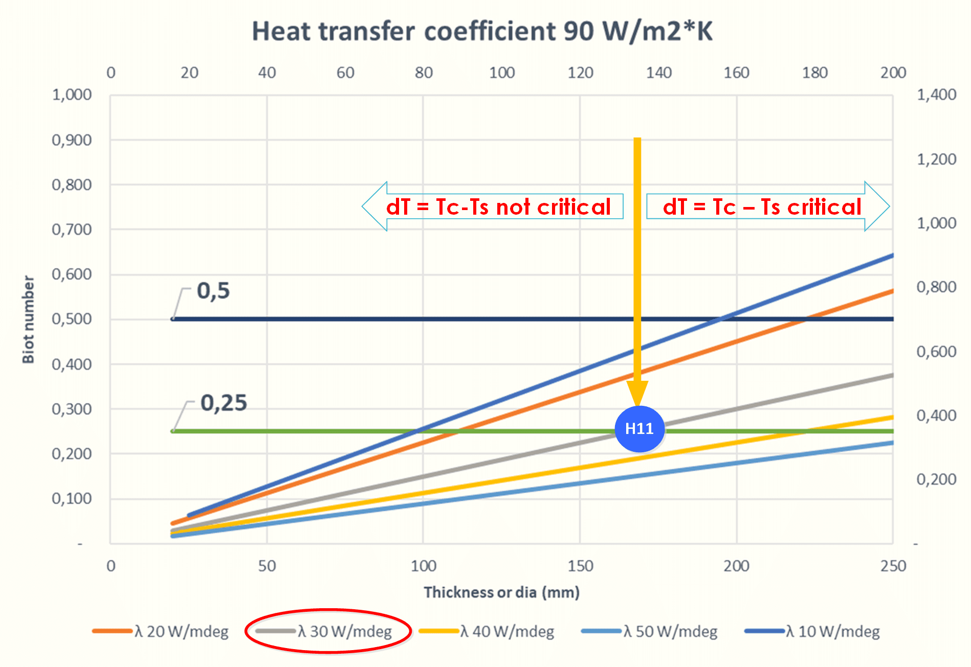
Fig. 3 – Cooling process of parts in 5S mode
Fig. 4 – Dependence of the Biot number on the thermal conductivity and the size of the parts
The question remains how to find out if an isothermal holding is necessary and whether we can predict it in advance. We know from the heating theory that there is a so-called Biot number (Bi). This number is expressed by the relation
Bi = L * h / λ
where L is the characteristic dimension of the body (m), h is the heat transfer coefficient between the heating system and the surface of the part (W*m-2K-1)) and λ the thermal conductivity of steel (W*m-1K-1). If the Biot number is less than 0.25, then it is a thin body, and there is no need to deal with the isothermal holding. Due to the shape parameters of the parts, the temperature difference between Tc and Ts will never lead to stresses that could lead to cracks. If the Biot number is in the range 0.25 <Bi <0.50, then we are in the so-called transition area, where critical stresses may or may not arise. However, if Bi> 0.5, then from the point of view of the heating theory it is a thick body, and there is always an isothermal holding.
Figure 4 is a graph of the dependence of the number Bi on the thermal conductivity of the material and on the characteristic dimension at the estimated heat transfer in the furnace 90 W*m-2*K-1. For H11 steel, the thermal conductivity is approximately 30 W*m-1*K-1. Since the curve intersects the limit Bi> 0.25 for dimension L ≈ 170 mm, if hardened inserta with dimensions below this value are quenched, the isothermal holding does not have to be used, if they are with dimension L > 170 mm, then the isothermal holding should be included.
The need for an isothermal holding can therefore be partially predicted on the basis of the Biot number, but this is not an ideal way in practical hardening. A better way is to measure Ts, Tc and dT, and monitor directly by the furnace control system whether dT is greater or less than 110 °C. This is the value specified by the Nadca 207 specification, which ensures that the stress from the temperature difference does not exceed the strength limit of the material.
In order for this to work in practice, a sophisticated control system is needed, continuously evaluating Ts, Tc and dT, which in connection with these values then controls the variable speed of the hardening turbine, holding times or limit temperatures needed to move the program to the next step. Everything has to happen automatically; in this critical phase of the cycle, it is difficult to intervene in the cooling process manually.
Proper programming of the isothermal holding step has one major advantage. Regardless of the Biot number, if at the limit temperature, e.g., 450 °C, the difference is Tc – Ts < 110 °C, the isothermal holding will not occur, if Tc – Ts > 110 °C, then it will occur. So, we don’t have to deal with theoretical Bi calculations, we leave everything only to the furnace control system. For hardening of parts, one program of type 5S will suffice, and only the difference between Ts and Tc will decide whether it is direct hardening or hardening with an isothermal holding.
An example is shown in Figure 5. Model curves for quenched a part measuring 450x300x200 mm, weighing 205 kg, with and without isothermal holding are compared here. On the left is the case where dT <110 °C. Because one of the conditions for ending the isothermal holding is fulfilled, i.e., dT <110 °C when the set delay temperature of 450 °C is reached, the actual isothermal holding time is zero.
On the right side is the case when the isothermal holding temperature is reached with dT > 110 °C. In this case, cooling is interrupted until the dT drops below the set value. In our example, it is after a holding time of 15 minutes that a dT < 110 °C is reached. The blue line marked as 500-600 °C represents the border between the plastic and elastic state of the material. Above this limit there is a low risk of gross cracking, below this limit the risk is high.
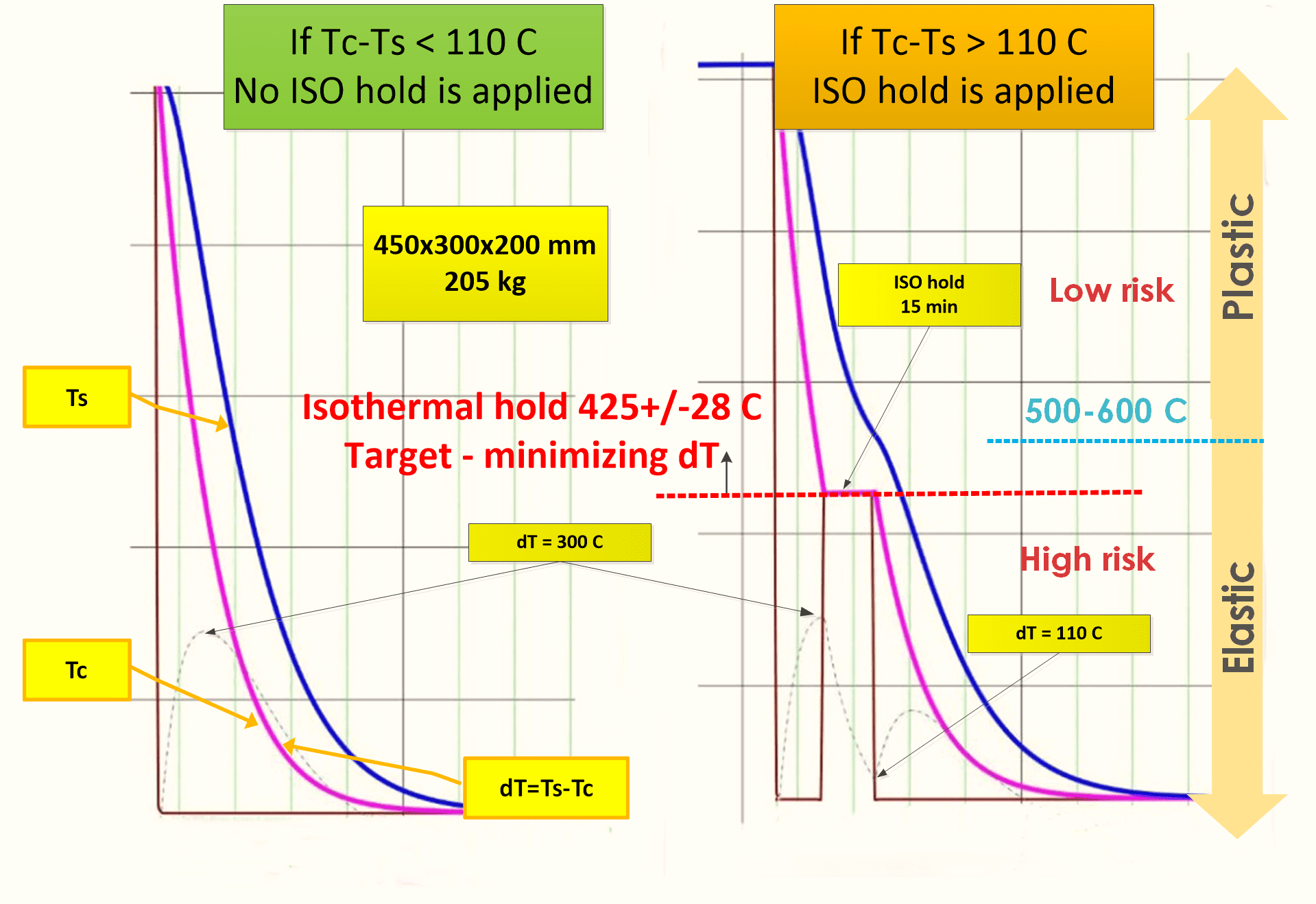
Fig. 5 – Example of program decision whether an isothermal holding will be applied or not
After the isothermal holding, the cooling in step S3 continues in the same way as it was set before the isothermal holding. This is also specified in Nadca 207. Thus, the overpressure in the furnace does not change, and if for step S1 it has been set to e.g., 5 bar overpressure, then this overpressure should be maintained in both step S2 and S3. Only when the temperature at 150 °C has been reached on Tc the step S3 is terminated.
For the next cooling steps, we must choose a compromise between the Nadca 207 recommendations and the furnace safety setting. Usually, if the temperature of any furnace thermocouple is not lower than 100 °C, the furnace door cannot be opened and the batch unloaded for safety reasons. But Nadca 207 says that if the temperature Tc drops below 150 °C, we complete the cooling in the open air, until Ts <50 °C. From the above, it can be seen that after completing step S3, the furnace cannot be opened and the batch removed without bypassing the safety principles.
Therefore, we have to insert another step S4 into the program, which will cool the batch to Tc <100 °C which is the safety limit for door opening. However, because cooling must be slow at this stage, we will reduce the overpressure in the furnace to 1 bar absolutely, i.e., to atmospheric pressure, and we will also reduce the speed of the cooling turbine to a minimum.
This slowing down of cooling is important because a phase transformation from austenite to martensite takes place inside the quenched part, and since the crystalline lattice of martensite is larger than the austenite lattice, this change results in an increase in volume and an associated increase in stress. In critical cases, the stress from dT and this phase transformation may be superimposed, resulting in large cracks.
The last step of the hardening cycle is step S5. Although it already takes place outside the furnace, on the external cooling station, it has a fundamental effect on the time if we were to start tempering. Some recommendations state that tempering should start as soon as possible after quenching, others within 1 hour, and others then e.g., from 8 to 24 hours depending on the characteristic size of the parts.
However, the problem with the heat treatment of inserts for die casting is that they are usually large pieces, and after removal from the furnace, the phase transformation from austenite to martensite is not yet complete. It can be assumed that up to 50% of austenite is still present inside. Therefore, it is necessary to wait for its transformation to take place. Acceleration of this cooling phase is undesirable. If the quenched parts are prematurely placed in the tempering cycle, they could crack precisely because the phase transformation accelerates when the tempering temperature rises and the increasing volume of material in combination with dT can lead to catastrophic cracks.
In practice, this problem is solved by attaching a magnetically clamped thermometer to the cooled part, which measures the surface temperature Ts, and only when the surface temperature drops below 50 °C can the part be tempered. This post-cooling process can take up to several hours and needs to be considered. Nadca 207 does not say whether this process can be accelerated on cooling station by forced air flow, but GM’s specification for the production of die casting dies, called AMTD DC-2010, directly prohibits this.
However, because the whole post-cooling process is already outside the furnace, it is not part of the hardening cycle record and must therefore be recorded differently. For example, by manual recording of the furnace operator in the production order about the time when the temperature Ts = 50 °C was reached, or by recording in the thermometer journal, where the number of the production order is recorded with information when the parameter was achieved.
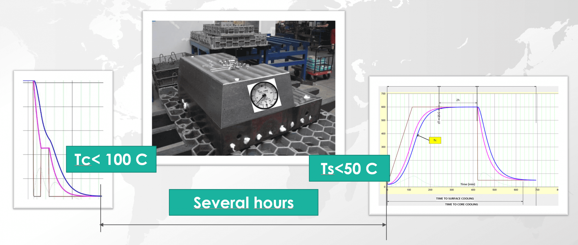
Fig. 6 – Method of after-cooling of parts outside the furnace
In conclusion, it must be said that in many cases we are heat treating very complicated parts, where there is a high risk of large cracks due to superposition of stress due to temperature difference and transformation of austenite to martensite. However, since only the parts of the die casting mould need to maximize the mechanical properties, i.e., the impact strength, in other applications it is possible to consider adjusting the cooling cycle by slowing the cooling speed. As a result of this slowdown, we will have a larger share of bainite in the structure, but the stress distribution will be more favourable. This is especially true for plastic moulds, where instead of resistance to thermal fatigue, the requirement for, for example, polishability predominates, and where a larger amount of bainite in the structure does not endanger the tool life.
If we have a well-prepared programming tool for programming the isothermal holding, it is therefore advantageous to include a second isothermal holding, above the line martensite start Ms. This further slows down the cooling and equalizes the temperatures between Ts and Tc. In this case, the cooling cycle no longer has 5 steps, but 7 (Fig.7).
It is up to each heat treatment plant to deal with these pitfalls, but without sophisticated cycle control software, this is not possible. On the contrary, with such a programming tool, the possibilities of high-speed quenching in gas (HPGQ) and at the same time the safety of hardening for the customer are significantly extended.
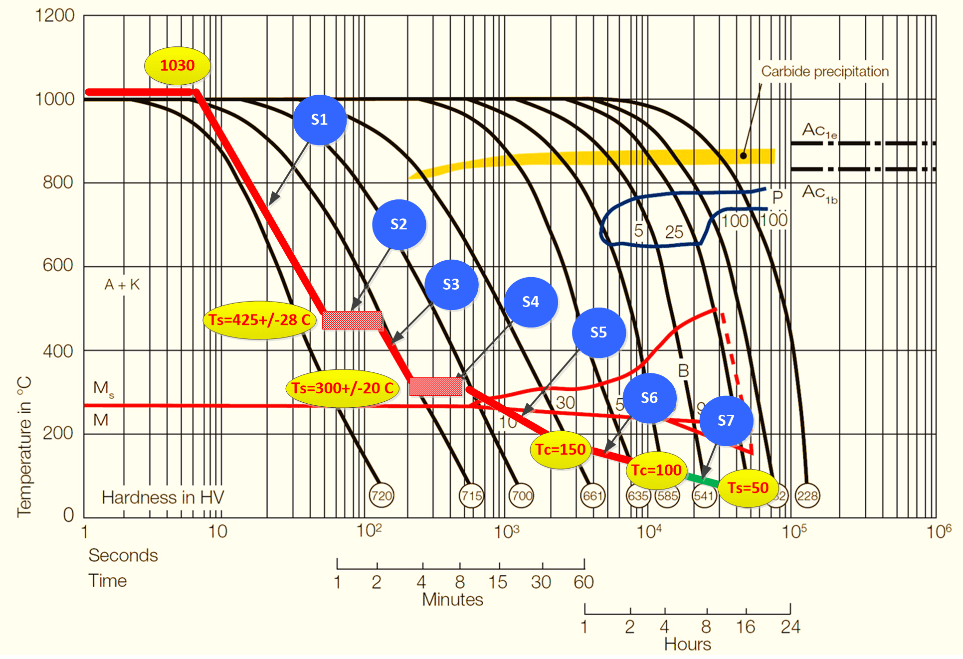
Fig. 7 – Cooling cycle in 7S mode
13th of September, 2021
Jiří Stanislav