Nadca 207-2022 – Thermocouples placement

Not so long ago, I visited a major manufacturer of die casting tools. When I spoke with the designer, I asked him how he designs the hole for the batch thermocouple Ts according to Nadca 207. He looked at me in amazement and then said: what do I mean by that?
It’s about the same as if the heat treater ignored AMS 2750 and furnace pyrometry. It’s incomprehensible to me, because on the one hand I’m still dealing with complaints about how the dies don’t last, how they crack, and on the other hand I’m not even doing the most basic things that should help me in my efforts.
Just to repeat the circle. Die casting foundries working for the automotive industry should voluntarily adhere to CQI-27. CQI-27 says that the purchase of material and heat treatment must be done according to Nadca 207, today in version 2022.
Nadca 207-2022 states that furnaces for hardening die casting dies must comply with AMS 2750 or CQI-9. If the stills didn’t do that, the die-cast foundries wouldn’t be able to work.
On the other hand, Nadca 207-2022 says that in order for the inserts to be properly heat-treated, we must control the die temperature from Ts and Tc, and above all, the temperature Ts must then be shown on the records as evidence of achieving a minimum cooling rate of 28 C/min. It is further stated that the responsibility for preparing the hole for Ts rests with the tool manufacturer. But he makes a dead bug.
Maybe I was unlucky, I met a designer who just happened to know nothing. So how should it be?
Nadca 207-2022 – page 6, article C, Thermocouples placement :
A dedicated thermocouple hole for placement of the surface thermocouple (Ts) is required. The hole should typically be 1/8” to 1/4” (3.2mm to 6.4mm) diameter, depending on thermocouple wire used and should be 0.625” 0.125” (15.9mm 3.2mm) deep. Placement of the surface thermocouple is to be in a controlling cross section and the thermocouple is to be accessible during the heat treatment process.
- The surface thermocouple (Ts) hole should be located in the center of the largest area of the die in the backside and should be at least 1/4T x 1/4W or mid-radius from the nearest corner.
- The core thermocouple (Tc) should be placed as close to the center of mass as possible using existing coolant holes. In cases where core thermocouple placement is not possible, the furnace load shall be controlled from a load block that represents the maximum thickness of the die with a thermocouple at the center of mass.
- If a waterline hole is used for a thermocouple, it shall be packed with a fiber refractory material to prevent direct contact with quenchant.
- Thermocouple wires must be secured to prevent movement during quenching.
- If multiple blocks are hardened in the same load, thermocouples should be placed in the block with the largest cross section.
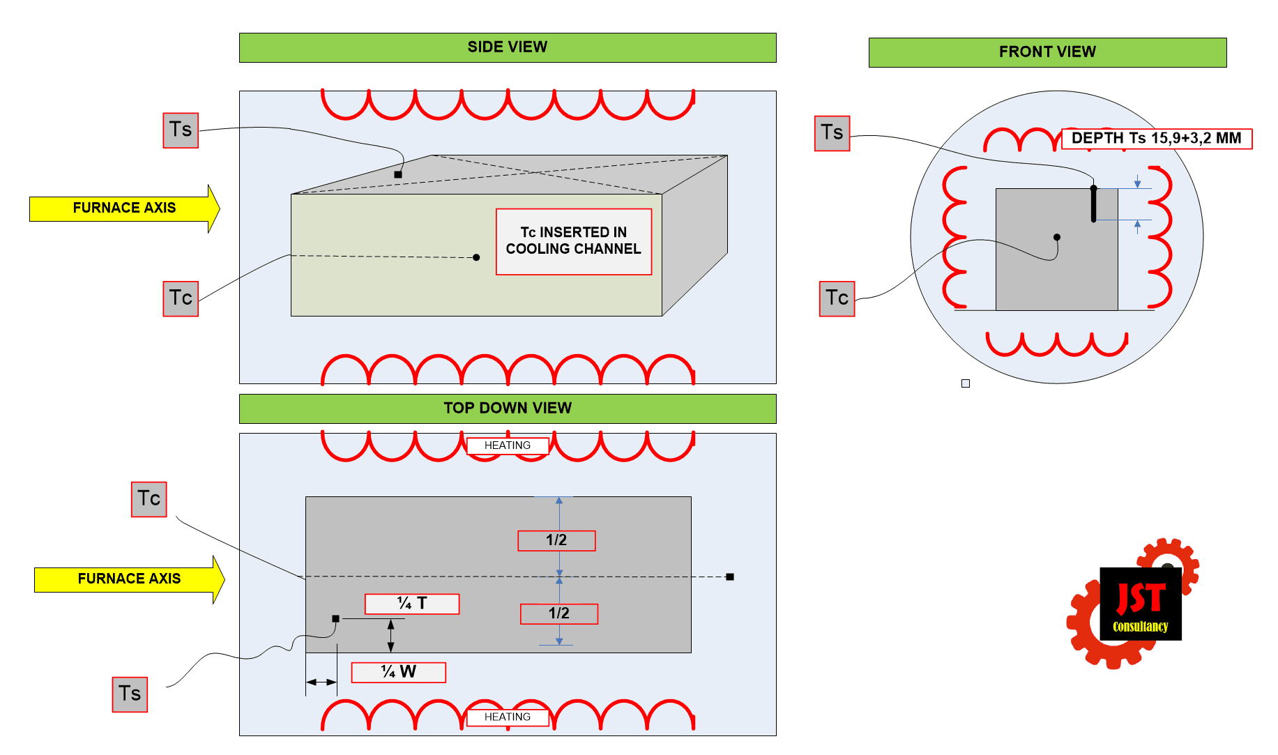
Fig. 1 – Example of placement of thermocouples Ts and Tc for one die in the furnace
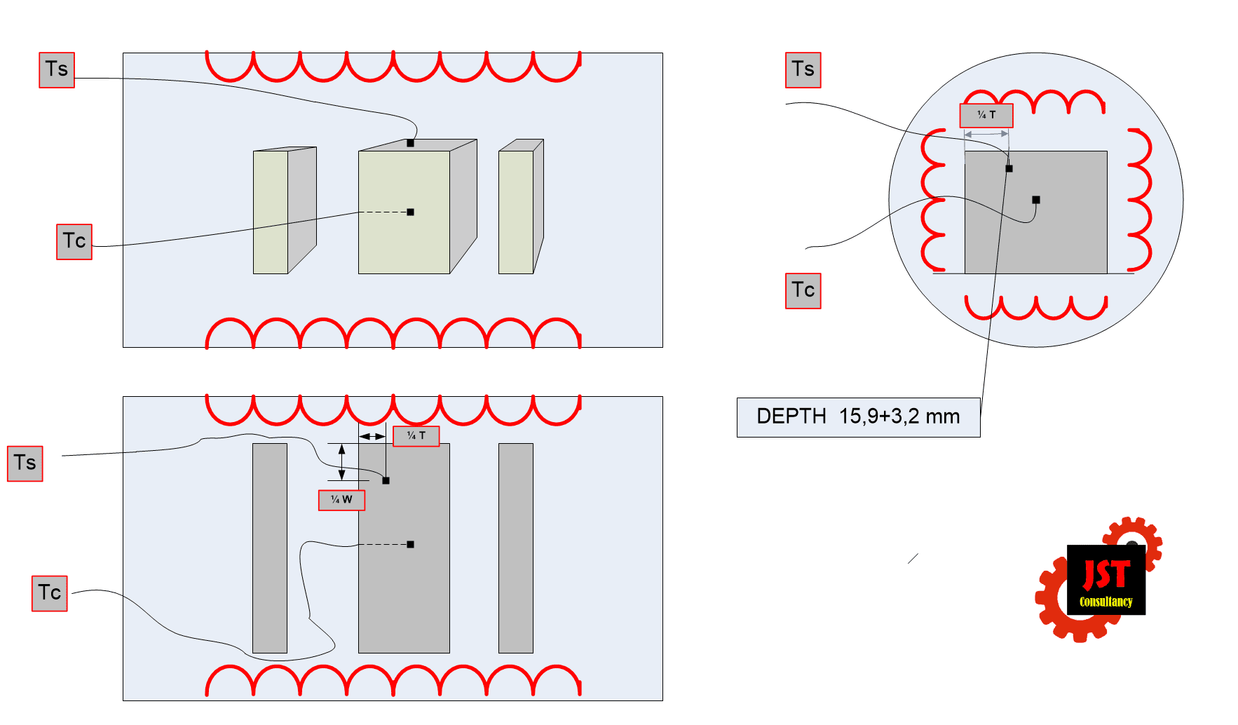
Fig. 2 – Example of placement of thermocouples Ts and Tc for multiple dies in the furnace
With multiple pieces in the furnace, it is assumed that if we measure the largest die and its cooling rate, the other smaller, unmeasured pieces have a cooling rate equal to or greater than the measured piece.
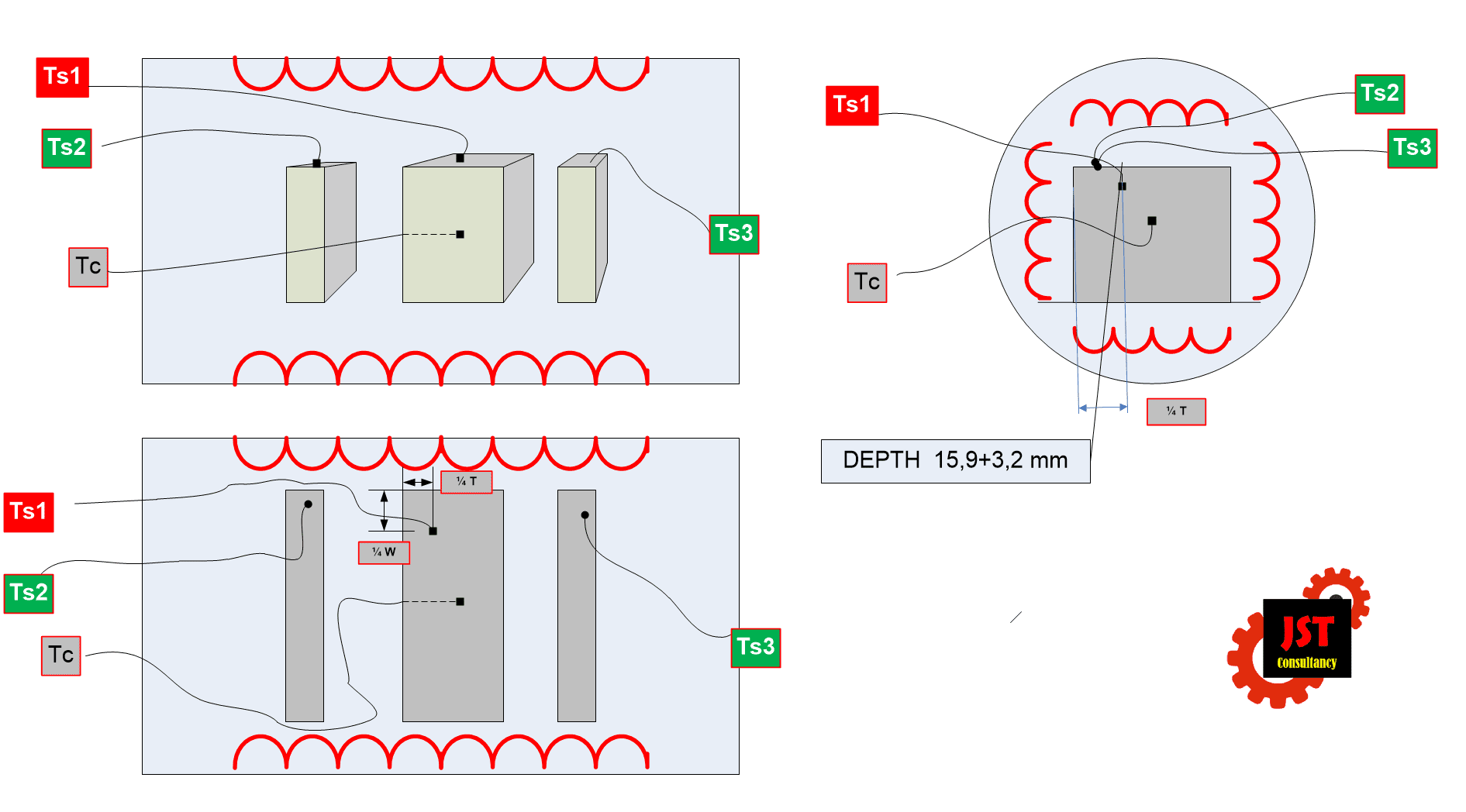
Fig. 3 – Example of thermocouples placement Ts1 a Tc and multiple thermocouples Ts2 , Ts3 ect.
However, since vacuum furnaces have evolved, today’s usual design allows the placement of at least 9 batch thermocouples. The reason is not Nadca 207, but preparation of the furnace for periodic TUS. Although only one Ts and only one Tc placed in the largest piece can be used to control the isothermal hold, the remaining thermocouples Ts2, Ts3 … Ts9, can be used and accurately measure the temperature of other parts as well.
February 10, 2023
Jiří Stanislav